
L9 - Retaining Wall Block With Lip
L9 - Retaining Wall Block With Lip
The L9 RWB has the ideal weight to size ratio and is designed to build strong, heavy duty and high retaining walls.
Available Colours
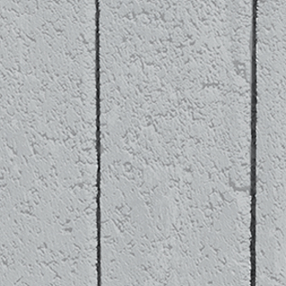
GREY
Product Finish
- Smoothface





Specifications
PRODUCT CATEGORY: RETAINING WALL BLOCKS
ENVIRONMENTAL RATING: CONTAINS ONLY LOCAL MATERIALS AND CEMENT
(LxWxH): Length 330mm x Depth 320mm x Height 200mm with 12mm lip
COMPRESSIVE STRENGTH: 14 Mpa
MASS: 28 Kg
NO / M²: 9 (205mm max. wide gap between blocks)
INFILL VOLUME: 0.012 (M³)
WALL MASS: 414 kg/m2
FRICTION CO-EFFICIENT: N/A
ENVIRONMENTAL RATING: CONTAINS ONLY LOCAL MATERIALS AND CEMENT
(LxWxH): Length 330mm x Depth 320mm x Height 200mm with 12mm lip
COMPRESSIVE STRENGTH: 14 Mpa
MASS: 28 Kg
NO / M²: 9 (205mm max. wide gap between blocks)
INFILL VOLUME: 0.012 (M³)
WALL MASS: 414 kg/m2
FRICTION CO-EFFICIENT: N/A

Open Face Lip Block
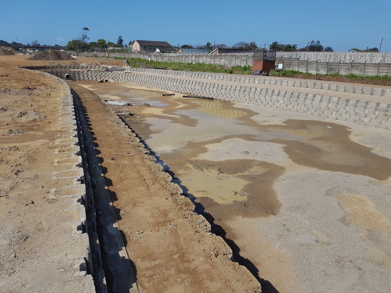
To address the many inquiries from engineers and from installers about a lip block, the GreenLock team has developed the new revolutionary GreenLock HEAVY DUTY L9 LIP BLOCK. The “L” stands for lip and the 9 for 9 blocks/m2 when the L9 is laid in an open face lay out (with a gap between the blocks).
The L9 blocks incorporates not only the essential and usual features of an open face lip block presently on the market, but has new design qualities never before used or seen. Although retaining walls look simple to install, there are many factors and criteria’s to consider to assure that the wall will be constructed correct to prevent a possible wall failure.
We at GreenLock think it best to always use the advise and / or services of a qualified engineer to make sure your wall will not fail and last forever.
Features and advantages of the L9 Lip Retainer Block
The L9 RWB has the ideal weight to size ratio and is designed to build strong, heavy duty and high retaining walls.
2. The overall dimensions of the L9 are :
Wide = 330mm
Deep = 320mm
Height = 200mm high,
Height of Front Lip 12mm
See the Specification table for more details
When laid with a 205mm open gap or with a slider, one needs 9 blocks/m2 and when laid without a gap 15 blocks/m2.
3. For optimum tensile and compressional strength the block has an increased wall thickness of 50mm, tapered to 55mm. At high tensile areas the wall thickness of the block is increased to 70mm/75mm.
4. The 320mm block depth provides important weight at the back of the wall where it is most needed for wall weight and stability. Most of these type of lip blocks with an open face layout, lack that depth penetration into the embankment.
5. The weight of the L9 RWB without the slider is 32kg. The slider weighs 6 Kg. The length of the slider is 205mm, which also determines the maximum gap between the blocks when laid in an open face layout without a slider.
The slider has an added advantage of having a weep hole on top and in the centre of the slider, providing each block/slider assembly with it’s own weep hole for added drainage.
6. When the L9 is laid without a gap and direct next to each other in a straight line or in curves, the L9 has a unique positive interlocking feature between each block, guaranteeing intimate contact and perfect front face alignment between the blocks at all times. This design registered interlocking feature will also increase the stability of each row laid and at the same time also strengthen the whole retaining wall. The positive interlocking between each block is achieved through female and male nibs placed vertically on the side of each block.
7. To further increase wall stability the L9 is making use of the unique and revolutionary new GreenLock anchorage system. Two grooves run parallel to the front face of the block and are placed near the back of the block top surface. This groove arrangement enables one to place a inexpensive 6 to 12mm round steel bar, Y6 up to Y12 reinforcing rod or such, into the groove to anchor each block to each other. In addition each block row can be secured into the embankment by simply using a polyurethane, or 8 gauge galvanised wire, at predetermined intervals tied around the steel bar and at the embankment around an anchor/pipe driven into the soil/embankment, or wrapped around a L9 block filled with a weak cement mix, at any allowable distance, either into virgin soil, soilcrete or into the compacted backfill.
8. Whether the L9 block is laid with or without a gap, each row of blocks is interlocked and anchored to each other through the steel round bar, Y-reinforcing rod or such. This type of anchorage is very effective, inexpensive and simple to use.
The design has been registered and is unique to the GreenLock retaining wall blocks.
9. Convex curves in retaining walls are usually weaker then concave curves. To be able to anchor the convex curved wall as well with a steel rod an indent has been placed at the back of the block centre on the top surface. This groove allows the polyurethane rope, or the 8 gauge galvanised wire tied around the round bar or a Y-6 (for easier bending into a curve) reinforcing bar, to pass through the block surfaces, because the gap provided for by the angled sides when the blocks are laid in a straight line, is now closed when the blocks are laid in a convex curve.
10. The L9 has a 55mm wide x 12mm high front lip allowing a wall angle of approx. 70 degrees. When the blocks are laid with a slider
the wall angle can be changed to either 62 degrees or 52 degrees. This is achieved because the slider has also a 12mm high lip in line with the block lip. The next block row laid on top of the slider can than rest against the lip of the slider.
When the slider is placed back by one vertical groove/nib (the 4 vertical female and the 3 vertical male nibs at the side of the block) the wall angle is approx. 62 degrees and and when placed back by one more groove/nib, the wall angle is 52 degrees.
11. The infill volume of the block is 0.012 m3. Please note that the L9 has on purpose no centre rib wall. The main reason is that the soil cavities of blocks with centre rib walls have smaller infill volumes and heat up the soil more through the sun and therefore hinder proper plant growth. In addition the increased wall thickness of the L9 block allow easier material fill during the manufacturing process, obtaining therefore a far better compaction rate, resulting in an increased Mpa strength and tensile strength.
12. The L9 has a well defined floor at the front to prevent soil wash out when the blocks are laid with a gap and without a slider.
13 For laying out a perfect and accurate convex curved wall, the blocks are tapered and maintain at all times intimate positive interlocking through the male and female vertical nibs placed vertically on the side of the blocks. Each consecutive block row laid will have a smaller radius and therefore the blocks can hinge around the 1 female and 1 male vertical lip placed at the back of the block. (see paragraph 14)
14. For smaller wall curves less than the curve provided for by the angled sides, the blocks can “hinge” either around the single female and the single male nib positioned vertically right at the back of the block for convex curves, and for concave curves “hinge” around the first front female and male nib at the front of the block. That way the blocks are always aligned perfectly.
15. The L9 can circumvent trees, manholes or other obstacles by simply using the vertical interlocking grooves / nibs to set back or set forward each block by either 40mm or 80mm (pitch of the male and female nibs is 40mm). The face of the blocks are thus always facing parallel to the wall face and provide a stronger, and perfect formed wall indent or protrusion.
16. To set out a perfect convex curve when the blocks are laid with a gap, with or without a slider, one can place in the first “set out” row of blocks laid, a slider in the front and one at the back of the blocks. (the slider at the back is turned around with the lip facing verical male nibs) Thus the slider acts as a spacer. That way the curve is perfectly formed and laid out. All consecutive block rows are simple laid against the block lip with either a slider placed at the front of the block or without a slider.
17. Setting out the first block row when the blocks are laid with a gap and where a slider is not required, use a slider as a distance piece to form an exact gap length between each block.
18. There are 3 vertical inverted grooves placed on the front face of the block. The centre groove is a marker to lay each consecutive row of blocks exactly over the block joints of the block row underneath when the blocks are laid without a gap, or directly over the middle of the slider when the blocks are installed with a slider. For this purpose the slider has also a protruding vertical marker in the the centre. The 2 outer grooves on the block face have a pitch of 205mm which is also the max. gap the blocks can be laid with an open face, either with or without a slider. The length of the slider is also 205mm. Each consecutive block row laid is than placed exactly in the centre over the 205mm gap using the 2 outer grooves on the block face as a template. The 3 vertical marker grooves are there to help the installers to form an evenly distributed and fluted wall face resulting in a beautiful and balanced looking wall.
19. For extreme high, stable and solid walls the L9 can be designed and laid in double or multiple rows of blocks to increase the wall weight as well as to prevent over movement in extreme conditions. If required the blocks can easily be vertically reinforced and filled with concrete.
20. The L9 has been designed and engineered to be stacked and transported without pallets using a grab truck. Thus the stacks can be easily stored, counted, shrink wrapped or strapped, resulting in quick loading and off loading without pallets left behind.Building sites are kept tidy and free of unsightly collapsing stacks and unnecessary breakages. Trucks can offload and move off site quickly without hindering building activity.
21. The finished GreenLock L9 installed retaining wall, laid with or without a gap, with or without a slider, are stable, strong, durable
structures and aesthetically pleasing to the eye.
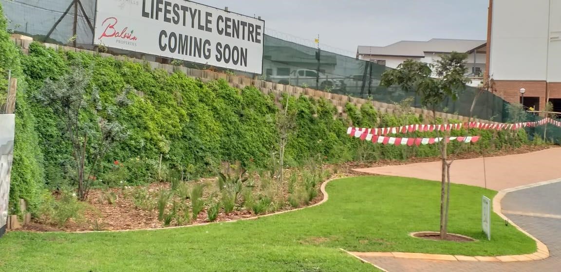
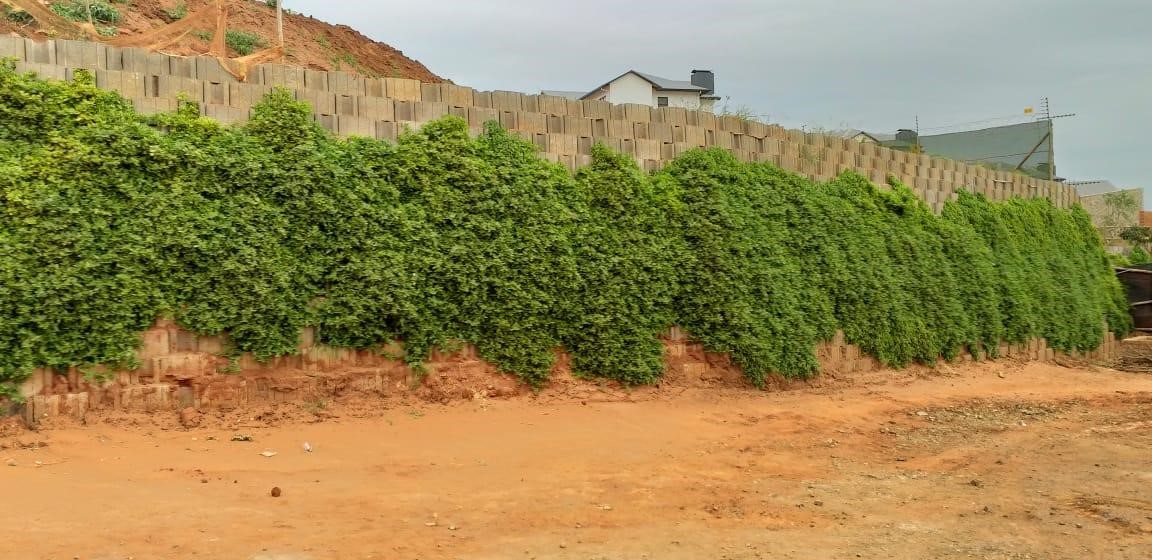
22. The L9 can be planted in all possible layouts, except when the blocks are laid next to each other, without a gap.
23. We at GreenLock always advise to use the services of a qualified civil engineer to design any retaining wall higher than 1.2m.
That way you are sure the wall will last forever and importantly, falls within the required Municipal guide lines and regulations. A proper engineer designed retaining wall will further help to prevent any future possible wall failures due to wrong installation.
Installation Guide
Planning :
Measure the length and height of the proposed wall and multiply these two numbers to calculate the square meter surface area.
For the open block layout and/or using a slider, multiply the number of square meters by 9 for the L9, alternatively when laying the blocks direct next to each other, by 15 for the L9, to obtain the number of blocks required either for the L7 or L9 GreenLock RWB (excluding possible cutting and/or wastage).
A rule of thumb is, where the wall is less than 1,2m and built to a batter of 75° (from horizontal) and where soil and drainage conditions are good and well compacted, there should be no need for an engineer. Where however, the height of the wall exceeds 1,2m, or if problem soils (clay) or a high water table exists, or where a structure is to be erected on top of the retained fill close to the wall, or even load bearing walls, then the services of an engineer or competent person are required. In such cases, the local authorities should insist on a design and stability certificate from the engineer.
Typical Installation :
Measure the wall layout & mark the course using string and stakes. In the closed layout the L7 and the L9 block is self aligning. Dig a trench 400mm deep, 700mm wide for single skin walls and create either a compacted gravel or a concrete base 300mm deep. (Gravel foundations are usually sufficient for walls under one (1) meter in height) It is imperative that the foundation is level in all directions. For additional wall strength the foundation top surface may have a max. of 5 degree angle slanting towards the embankment.
Place first row of blocks onto the foundation, whichever layout is chosen, ensuring that the blocks are spaced with the correct spacing for the open layout and without slider and that for the closed layout the interlocking ends of the blocks mesh as closely as possible. The blocks must be placed level in all direction on the foundation. If the foundation surface is sligthly angled towards the embankment, then the blocks should follow that angle. For additional wall strength the first block row should be imbedded in a mortar bed and the blocks and cavities filled with a weak concrete mix.
Place a flexible perforated drainage pipe, 75 – 110mm in diameter, behind the first blockrow above ground level and wrap this in filter fabric. Ensure that 19mm gravel is wrapped in filter fabric around the drainage pipe. The gravel layer should be at least 400mm wide and 220mm deep.
Please note that for proper drainage the drainage pipe assembly must be placed slightly higher than the ground surface area in the front of the retaining wall. Drainage outlet pipes, connected to the main drainage pipe, should be installed intermittent and in accordance to the length of the wall, allowing any accumulating seepage water behind the wall to escape freely.
“OFF SET”
The L7 and the L9 are automatically spaced correctly if the slider is used and/or if the vertically placed front face groves are used, if the open face layout is used. For more information please read the detailed information in paragraph 18 above.
For the L7 and the L9 retainer block it is important that the OFF SET dimension is always in accordance with the chosen layout used and that with each block row laid that the same dimension is maintained. If one follows this advise the finished wall will look stunning, aesthetically pleasing and important for the eye, with evenly fluted joints. If one does not follow this rule, the wall will not be weaker but it will visually look untidy and create a “dizzy” look.
Important Note:
The joints between the blocks, whether laid with or without a gap or with or without a slider, each block row will automatically form an evenly distributed fluted pattern over the whole length and height of the finished wall. To achieve different wall angles, refer to the L9 and L7 PRODUCT specification and write up to select the reqired wall angle. Because of the front lip on the block and on the lip on the slider, both the the L7 and the L9 have three adjustable wall angles to choose from.
Please read the detailed information provided under the PRODUCTS column for the L7 and the L9 retainer blocks. Remember to fill all blocks and cavities with top soil before the next block row is placed if these are to be planted, and to compact the backfill as much as possible and the fill in the blocks only slightly. Behind the RWB wall there should be a layer of minimum 300mm wide of compacted drainage material, such as free draining sand. Compact the backfill of not more than every second block row laid.
For the L7 and L9 RWB it is not necessary to install geofabric on compacted backfill to wedge between the blocks. The L7 and the L9 has unique additional wall anchor possibilities by using horizontally placed reinforcing Y-bars in the grooves inbedded on the top surfaces of the blocks. For detailed and additional information please read the information under PRODUCTS information for the L7 and the L9 retainer blocks. 9